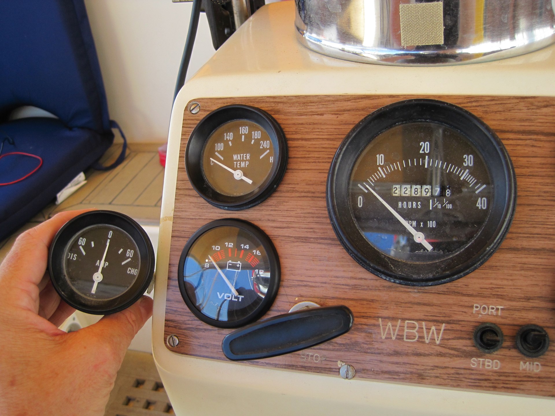

Things we find. Example: the old binnacle ammeter was both poorly installed (i.e. loose wire) and partially disconnected when I installed the new alternator (see "We Got The Power").
We did notice that the ammeter seemed to be stuck on zero.
Then, as I thought about it, the idea of a binnacle ammeter for a 110A alternator started to give me the creeps.
Running the expected AWG #4 wire up to the tiny binnacle ammeter and then back to the batteries seemed a bit crazy.
This adds something like 16 feet to the run, meaning that we'd have to move up to AWG #2 copper Anacondas.
And, of course, binnacle ammeters only go to 60A; the alternator could produce almost twice that under high RPM's.
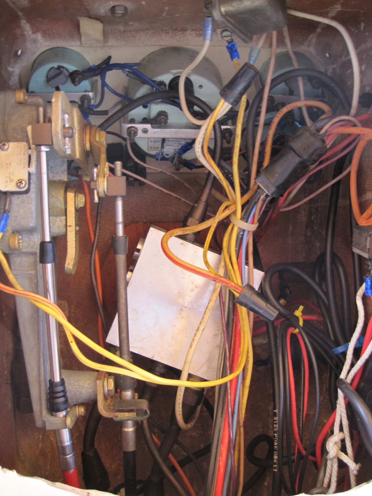
Further study showed that there used to be an even longer wiring run from alternator up to the binnacle then down to circuit-breaker panel and then back to the batteries. This kind of run is the definition of voltage drop.
During the power rework, I had already cut part of this (alternator to engine wiring harness) when installing the new alternator.
Continuing to wring my hands over the dysfunctional meter, I looked in the catalogs (like West Marine) and saw that "Heavy Duty" binnacle ammeters are not very common. Voltmeters appear to be more popular. Clearly, this is because a voltmeter is little more than two small wires to the key switch and ground.
The bottom line is that I could easily install a voltmeter, and also remove yet more unused wiring. This is a tiny simplification.
Change Impact
Another consequence of the alternator upgrade is that the tachometer is no longer correct. The old wheel was about 3.5" in diameter. The new wheel is about 2.5" in diameter. This ratio of about 1:1.4 suggests that the tach readings will be off by a factor of about .714. Tach says 1120, engine is idling at 800. Cruising RPM of 1600 will show as 2240 on the tach.
We purchased an inexpensive Neiko "Photo Tach" that uses a small laser to observe a reflective strip attached to a wheel on the engine. This gives us an accurate reading of engine RPM's that we can compare with tachometer readings.
In principle there's an RPM adjustment set screw inside the tach. It's hard to see the back of the tach without taking the instrument panel apart. Being lazy, it seemed like gathering data was easier than taking the binnacle apart — again.
Sadly. It's complicated.
We only have a few data points.
| Sample | Tachometer | Engine |
|---|---|---|
| 1 | 1000 | 883 |
| 2 | 1500 | 1242 |
| 3 | 1500 | 1217 |
| 4 | 1600 | 1306 |
| 5 | 1750 | 1534 |
| 6 | 2000 | 1805 |
| 7 | 2000 | 1720 |
Not really a solid basis for good science. However, it's really consistent, and therefore we can fit a regression line.

Here's a useful approximation:
The engine is 90 RPM's below 90% of the tach reading.
You can't read the tach more precisely than the nearest 100 RPM, so it's best to "round up" to the nearest 100.
Also, you can't set the throttle very accurately.
[The engine has a governor that limits it to 2500 RPM.]
In the appropriate range for cruising (around 1600-1800 engine RPM) the tach readings between the two models look like this.
| Tachometer | Engine |
|---|---|
| 1600 | \(0.9126 \times t - 92.94 = 1367\) |
| 1800 | \(0.9126 \times t - 92.94 = 1550\) |
Maybe a little laminated card like this:
| Tachometer | Engine |
|---|---|
| 1000 | 820 |
| 1200 | 1000 |
| 1400 | 1180 |
| 1600 | 1370 |
| 1800 | 1550 |
| 2000 | 1730 |
| 2200 | 1910 |
| 2400 | 2100 |
| 2600 | 2280 |
| 2800 | 2460 |
Or maybe I need to take the instruments apart to look for the set screw.