


A little touch-up
Rust never sleeps. Also. Rock and roll will never die. But that’s another story.
We had two problems leading to water on the engine (and rust.) One of the deck drain fittings failed, leaking rain water over everything. This was an amazing amount of water. All the snow-melt from the port side of the boat ran down through the broken fitting under the lazarette and onto the engine. And onto the top of the center fuel tank. It filled the bilge above the level of the fuel tank, floating the remaining diesel fuel out of the tank. While catastrophic, by the end of the summer, I eventually pumped the remaining diesel out of the center fuel tank. It’s now filled with ~100 gallons of snow melt and a little antifreeze.
The second problem was smaller. The exhaust anti-siphon loop got a tiny bit of crud in the little flapper valve. Crud is rare in the raw water intake, but it’s not impossible. There are calcium deposits and and a zinc that can leak large particulate into the raw water system. The bit of crud in the anti-siphon meant it leaked raw water in the engine room. The big, bronze anti-siphon comes apart with pliers. Inspection and cleaning is all that’s required to fix it. But. Raw water rusting things up.

In this picture of Mr. Lehman, I’ve removed the aft air cleaner, pushed a rag into the intake, and scraped as much loose paint as I could with a soft wire brush.
Theoretically, we should etch with some solvent, prime, and paint.
But.
For now, I’m going to cheat.
A can of Rust-Oleum IH Farm Implement Red will probably do about as well as a really professional masking, priming and painting exercise. The exhaust manifold is a giant cast-iron block. The rust can (eventually) eat through the metal, but I expect it would take decades.

We are dealing with exhaust gasses here, so a little care seems prudent.
(And a new carbon monoxide detector will also be a good idea.)
The color doesn’t match the original red perfectly. The folks at American Diesel in Kilmarnock told us not to spend a lot of money buying the Ford-branded engine paint. Rust-Oleum was perhaps better, and the Farm Implement red was a good match.
CA has a bunch of places that need additional touch-up. We’ll be masking and painting some more.
The “use in a well-ventilated area” doesn’t fit well with spraying paint inside the engine room. This means we like to paint just before we leave the boat. We’ll be touching up a little at a time.
Rust never sleeps.

It’s going to look like this
All the supports are inside the tank, screwed into the aluminum.
They’re more-or-less lined up, and they sit about as level as anything in a boat can sit. Which is to say, not level enough for billiards, but level enough that the olive doesn’t get knocked out of my martini glass.

Here are cardboard templates for the three parts of the upper bunk for the 35 gallon bladder.
The bottom 15 gallon bladder is back-ordered, giving me more quality to paint.
Ideally, I can get two coats on between Saturday and Sunday. Unless it’s so cold Saturday that we don’t want to go out to the boat.
Measuring the space (yet again) I see that it’s a very, very tight fit for these two bladders. I don’t think the bottom bladder can be filled completely because of the narrowness of the V.
We’ve never been able to use this tank. So a ¾-full 15 gallon bladder and a 35 gallon bladder is vastly better than what we have now.
For the fresh-water systems, we want to clean the starboard tank, and start tearing apart the port tank.
We can’t do this until we get the sails out of the saloon. Doing a job this big only on weekends is challenging. But. When I stack this against other people’s life challenges, this is hardly even worth complaining about.
When the bladder arrives, then we can clean it. Imtra has a cleaning procedure that’s very important.
Before using your water tank for the first time, partly fill the tank with warm water (122 ̊F/50 ̊C) and a 1% solution of mild detergent. After a few minutes, rinse with clear water and fill again with water treated with chlorine tablets (follow package instructions for a 5% concentration). Empty after 2 hours and carefully and thoroughly rinse with clear water. This procedure should be performed with the system fully installed so that all the piping undergoes the same treatment.
Maybe we’ll do this on deck where we can drain the bladder with gravity instead of the boat’s fresh-water pump.
They recommend cleaning every 6 months. Perhaps this means that I want to put a drain cock down in the bilge to let gravity drain the tanks during cleaning?
For long-term storage, they recommend 10% chlorine in a partially-filled bladder. This seems to be an insane amount of chlorine. We suspect this is really 0.1%. We suspect this is a good idea for the other tanks, also, and we’re going to try and remember to do this. It does mean keeping a close eye on water levels to judge how many chlorine pills to get to 10% chlorine levels.

A few more coats of paint...
Here’s where the forward tank bladders stand.

We’ve got hose and fittings.
We’ve got a lower shelf with some bilge paint.
I’ve cut the first of three parts of the upper bladder’s shelf. (I’ll post a picture next week.)
I’ve measured yet again and discovered that cramming a 24″×26″ bladder into the bottom half of the V-berth tank is going to be difficult. The space is almost large enough, but not really large enough.
The filler elbow at the top of the bladder will be jammed up under the shelf, and we’ll never get the full 14 gallons into the lower bladder.
The top 35 gallon bladder should work out acceptably, however. I’m installing supports and shelves as quickly as we can get them cut and painted.
Saturday we painted many things. Sunday it was too rainy, and we didn’t go to to Red Ranger to paint shelves. We’re making progress, but sometimes it feels like watching paint dry.

V-Berth Shelving
It’s supposed to work like this:

You can see the white supports. Two coats of bilge paint. Heavy-duty hardened steel self-tapping screws.
The taped-together piece of cardboard is the pattern for the shelf that sits down there. It’s much easier to build it with the supports screwed in. I didn’t take a picture of the plywood piece. But. I seem to have managed to get the supports close enough to level that the plywood sits down there solidly.
What a relief.
It was a little dodgy getting the supports all reasonably aligned and more-or-less “level”. It involves setting the spirit level up on the bunk to see which way we’re heeled and then moving it down inside the tank to parallel the angle of heel. While holding the board in place. While worrying about the height. While squatting on the aluminum.
There are 8 supports for the sections of the top shelf. They’ll go in while we watch paint dry on the bottom shelf.
Right now, there’s a lot of watching paint dry. The weather is cold enough that it’s one coat on Saturday and one coat on Sunday and then wait a week to install. For the little supports, I could more-or-less paint both sides by flipping them over when they were tacky. For the shelf, though, it didn’t get tacky before it was time to go.
It may take another weekend just to get it painted. Then we can start putting in hoses to see if the lower bladder will work out as planned.
The plumbing up to the deck was a 7′ run of 1¼″ hose. There was a 1″ pipe nipple under the deck. The outside diameter of 1″ copper pipe is 1¼″: you can slip a hose over it and slap on a hose clamp. I prefer proper barbs, so I’ll replace the nipple with a proper hose barb fitting. I’ve got new hose and fittings on order.
The bladders need to be washed and treated with a mild chlorine solution before use. Then we can pressure test the whole thing while we watch paint dry for the upper bladder’s shelves.

Sails and Sail Covers

Workarounds aren’t really a good idea. We worked around a number of mainsail problems for years. We’re finally past those not-to-smart compromises.
I don’t really have good pictures of the new sails. They went on late last year, and then came down for the winter, unused.
Here they are in the saloon. Waiting.
These include gorgeous — red — sail covers.
CA made the previous covers from the Sailrite “Stackpack” design. Sailrite has kits, of course, but they have a lot of information on building your own. https://sailrite.wordpress.com/tag/diy-stack-pack/ for some guidance.
The sailmaker came to take measurements of our main and mizzen last year, and commented that our main had a lot of slides. A real lot. This made the stack by the mast taller than it needed to be. They would not be using as many slides, and the stack would be shorter.
This explains why our original sail cover was so HUGE. CA never liked it, and we reworked it over the years, hemming it and putting in darts. All the usual tailoring things to get it to fit the sail better.

Here’s a picture of the new sails and their new covers. You can see the cover wraps tightly around the mast.
This would not have worked out so nicely because there was a mast step on the port side, right in the way. The previous owner had put them up the main. (We love them. But. There are issues.)
We had worked around the mast step by adjusting the stack pack. CA cut and hemmed a notch around the step. We worked out a way to lash the cover around and over the step.
The sailmaker said that a better idea was to remove it. Don’t work around it. Replace it with something smarter. Replace it with a folding aluminum step. See https://www.defender.com/product.jsp?id=1280218 for the Sea Dog step. The sail cover can lash down around and over this without any work-arounds.
Oh. Lesson learned: Don’t work around it; Fix it.
Fixing it, however, wasn’t easy. The steps have stainless screws.
I’ll repeat that for folks skimming.
The steps have stainless screws.
Each screw was oxidized into position more-or-less permanently. Using a wrench and a Phillips drive bit, I got one screw out. I spent days with penetrating oil. I used Vice Grips to mush the heads and twist until one head broke off. Leaving me no choice. Each screw had to be patiently drilled out. A 3/16″ TiN bit at slow speeds will (eventually) pop the head off the screw.
(Two batteries for the 20V DeWalt also helped: charge one while working the other.)

Finally.
This weekend it was warm enough to finish the job.
The Sea Dog mast step is (finally) in place.
Some big-old aluminum rivets seemed like a better idea than stainless screws. They make countersunk rivets using an I or a G drill bit (not a number, a letter.)
Rivets have better shear strength than screws, so this bad boy can hold up something like 1700 pounds.
So that’s the final “step” in the installation of new sails.
We’ll be bending them on some time in the next few weeks while we wait for paint to dry on the shelves for the V-berth water tank.

The Mizzen Bridle
Red Ranger's original mizzen setup had the mizzen sheet attached to a wire bridle that was shackled to the deck. Simple. Reliable.
But.
With shackles, it was difficult to press the bridle into service as a traveler. The mizzen, like the main, needs to he held down when off the wind. Because you can’t see it, it’s not as apparent when the boom is lifting and a vang would help the sail’s shape.
Some boats, like a Sunfish, use a bridle with a block that can alter the shape of the bridle’s triangle. I thought about this for a while, and opted not to try it. I suspected the Sunfish bridle is only there to leave room for the tiller.

What I did was get some of those big snap shackles, and a thimble, and made myself a moveable bridle. I could then adjust the height and mess with the positioning to see what I really wanted.
We used this for a few years. It was very nice to be able to adjust where the mizzen sheet ended.
For beating, I could move the the bridle to weather, and then ease the mizzen sheet exactly to midships.
(I’ve heard that it’s sensible to pull the mizzen even higher to help point closer to the wind. I haven’t tried this.)
For running, I could move the bridle off wind, using the running backstay’s anchor.
The picture may be confusing because there’s docklines running across the deck. And. Our fender board is tied into the taffrail with a whole bundle of docklines.
At this point, the size of the triangle seems about perfect, so, the old rope and seized thimble needs to go.
I have a coil with many, many feet of 3/16″ wire rope. I think, maybe, it was intended to be a spare shroud or stay. Knocking about 4′ off the end won’t — I hope — prove too large a problem.
I bought a pile of swageless fittings from E-Rigging.com (https://www.e-rigging.com/search.asp?keyword=51632205 and https://www.e-rigging.com/search.asp?keyword=51632105)
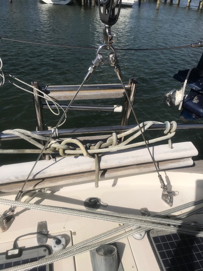
Now I have a mizzen bridle made with proper stainless wire rope, fittings, and shackles. Not a jumble of old dock line with a seized thimble. Once we get the water tanks in working order, we want to try this out.

Former V-Berth Tank Interior Prep
The remains of the V-Berth tank can hold two bladders. This requires a shelf. Since the bottom of the tank comes to a tiny little point, it requires two shelves: a top shelf that leaves 11″ of space and another shelf, 11″ below that.
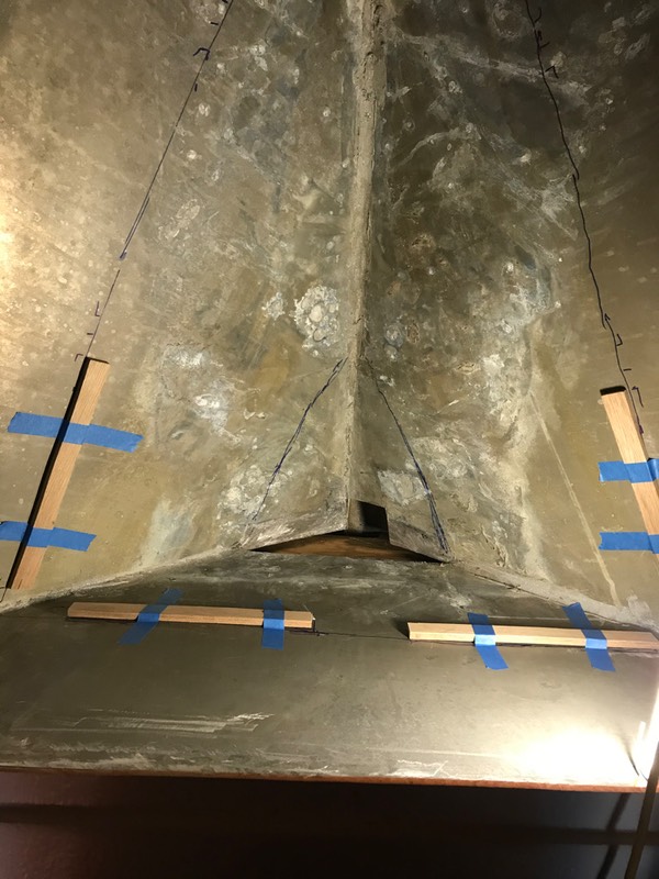
I’ve cut and messed around with some supports. I put them in with tape to see how it might work.
Once we have the supports in there permanently, we can cut a series of trapezoidal panels to make up the berth for supporting the tank.
The lower tank’s triangle (barely visible) is 14″ wide and 15″ along the bottom seam of the tank. The berth is not very big, but the bladder lays on this as well as the sides of the tank, so the bladder will be larger than 14″×15″.
The upper bladder’s bunk will be three sections, each about 13½” tall. One narrows from a base of 35″ down to 24″. The next narrows to 13″. The last will be almost a triangle; we’ll truncate the point and inch shy of the seam in the tank.
We cut a piece of cardboard to see what one of the bunks will look like. Without having the supports firmly attached, it’s premature to measure and cut the shelves.

Here’s the trapezoidal shelf pattern sitting on the supports.
The bladder can then sit on top of this shelf.
The space overall is nearly 39″ long, and three 13½″ pieces will fit leaving a little space up front for condensation, or leaks, to trickle down to the bilge.
The wooden supports need a thorough coating of bilge paint. We did the first coat this weekend.
It’s barely 16°C (61°F) so the paint will take over 24 hours to dry.
As of Sunday, the first coat is on. Next week, another coat of bilge paint on Saturday, and we can install the supports Sunday.

This will let us fine tune the cardboard pattern for the first panel.
So far, things seem to have been working out more-or-less acceptably. Not particularly good, but — more important — not particularly bad.
The cutting was a lot of loud work. But that’s in the past. I’m starting to put the tools away.
Measuring is fraught with difficulties because of the complex shape. I’ve stuck my measuring tape down there over and over to try and get sizing information. It’s difficult.
I think I have the right self-tapping screws to hold the wooden supports to the aluminum tank wall. Ideally, we’ll put these in next Sunday. Then we can start fitting cardboard patterns for real. We can cut and bilge paint the bottom panel, and start ordering some more parts.
Once the bottom panel has two coats of paint, I need to set the 14.5 gallon bladder down in the bottom, and see how things are working. This will involve building the full fill-and-drain setup for the single tank. As soon as the dock water is on, we have to thoroughly pressure test the lower bladder before we install the upper. It’s pretty well inaccessible down there.
I don’t want to get too far ahead of the lower bladder installation, in case there are changes we need to make.

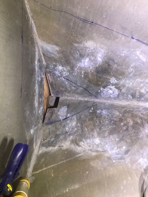
Water Tanks — Cut Once Measure Twice (?)
The usual advice is measure twice cut once. But. We’re not there yet.
I’ve (finally) cut away enough of the top to reach inside and work. While it’s taken a bunch of weekends, it’s really one, long messy cutting job.
We wait for afternoons where it gets up to about 7°C, so it’s quite chilly for poor CA who’s handing me tools and waiting to hear if I drop a running saw on my foot.
I can now plan the two shelves to hold the two bladders. If you squint, you can see the blue sharpie lines. One is 11″ down from the top. The other is 22″ down. They make neat triangles, I think.

The master plan is to screw some supports onto the sides of the tank along the sketched lines. Then I can set two triangles of ⅜″ plywood on the supports.
The bottom berth’s triangle is 12″ across the aft end and about 13″ tall. Almost equilateral. While the triangle isn’t large, a 25″×25″ bladder can rest on this bunk and the sides of the tank.
The upper berth’s triangle is 34″ across the aft end and at least 43″ tall, so a 26″×45″ bladder will fit up here, nicely.
I’ve got wood and self-tapping screws for the aluminum: McMaster-Carr lists the screws for tapping into aluminum as 90203A629. I need some bilge paint for the wood, then I can cut some strips to support the bunks.
Then we’ll cut some cardboard to be sure I’ve measured the awkward bunks properly. We can all nod and smile about the triangular shape, but this is a boat.
Once we’ve got a sense of exactly what the shape is, we'll lay the cardboard out on my plywood to try and figure out how best to make the pieces. The plywood is in 24″×36″ sheets, so getting everything to fit is tricky. See this: McMaster-Carr 1125T24.
After a coat of bilge paint on the wood, I’ll be able to throw in the bladders. Since the lower bladder will be nearly inaccessible, I need to plumb it first and test it before adding the upper bladder.
After testing the lower bladder, I’ll have to cut the filler line to add a “T”. It also means adding a “Y” to the drain lines to combine the two bladders.
In this picture, you can barely see the triangle cut out of the lower portion of the aft wall of the tank. That was intended for the drain hoses to exit. There’s not enough clearance for the tubing. And razor-sharp aluminum edges that are hard to file smooth.
Measure once. Cut twice.
So I had to cut an extra hole.
I can file the edges smooth on this access window, wrap them in foam insulation used for home water pipes and run the two drains down into the plumbing confident they won’t chafe through.
Part V? Cut the supports and paint them. If the weather’s nice enough, we might be back the next day to install them and start shaping the bunks. Putting in the tanks is easy; testing them has to wait for the marina to turn on dock water.
&media=http://www.itmaybeahack.com/TeamRedCruising/_Media/c2dd6877-39c5-491b-a366_med_hr.jpeg&url=http://www.itmaybeahack.com/TeamRedCruising/travel-2020-2021/water-tanks--cut-once-measu.html "Pin It")
Water Tanks — Part III — The Wreckoning
We’ve learned a lot of lessons.
First, the 4″ segmented TiN coated blade for the Fein Multimaster is the secret to this job. See this from Multifit Blades. The technique of scribing the line carefully with the blade oscillating, followed by running the tool slowly back and forth works really well. A little pressure is enough to start cutting a a layer of metal. Eventually, you break through the metal and can follow the starting line, finishing the cut.
The tank’s walls seem to be 3mm thick, about 0.13″, which makes it 8 gauge aluminum. The blades say they’re good to 11 gauge, so, we’re pushing things here. I did finish cutting a pretty nice 21″×21″ opening. I’ve deburred the edge, so it’s not razor-sharp. I have good access to the interior of the tank.

As you can see...
There’s a bit of yoga involved, since it’s barely 27″ deep. But I can fold up pretty compactly.
I tried some “blind” cuts: sawing up under the edge of the tank where you can’t really see what you’re doing.
The blind cutting worked out well, but you have to have a good grip on the tool, and a lot of patience. It’s not a thing where you can reach a long way inside the tank and hack away hoping for the best. You need to be close and solidly braced.
Originally, I thought I might be able to design a set of rigid tanks that would fill the space. That idea now seems way too complex. The more time I spend, the more I realize how constrained the space is.
The current thought is two tiers of flexible bladders. A piece of plywood can divide the tank into upper and a lower berths. Bladders tend to be less than 10½″ tall when filled, dictating the height of the layers in here. The pointy bit at the bottom-most 3″ can be blocked by a triangular floor. This leaves 24″ to be split into upper and lower berths for tanks.
I think it could be as much as 56 gallons, if I can find the right bladders. And if my estimates are correct. Pragmatically, it looks like the Plastimo 16658 is 115 cm long and 105 cm wide; which is close to the top triangle: 42″ long and 40″ wide at the aft end. This is 30 or so gallons. Underneath it is room for at least a 10 gallon tank; possibly enough space for a Natua FT911121 which is 14 gallons.
Next steps? Measure and mark the location of the shelves to separate upper and lower. Get some plywood and epoxy paint and self-tapping screws and build the shelf. Then. Bladders. Then hoses and hose-clamps.
And once that’s done?
The port side of the saloon has to come apart. That’s going to be (I hope) easier to get the top of the old tank completely off. And (I hope) easier to order a set of 4 tanks, each 33″×17.5″×11″. Many lessons still to be learned.

